

What Is The Effect Of Putting A Ferromagnetic Material Inside The Coil Of A Solenoid?

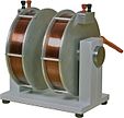
A unproblematic electromagnet consisting of a roll of wire wrapped around an iron core. A core of ferromagnetic cloth similar fe serves to increment the magnetic field created.[1] The force of magnetic field generated is proportional to the amount of current through the winding.[one]
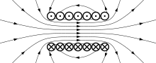
Magnetic field produced by a solenoid (curl of wire). This drawing shows a cross section through the center of the curl. The crosses are wires in which current is moving into the folio; the dots are wires in which current is moving up out of the folio.
An electromagnet is a type of magnet in which the magnetic field is produced by an electric electric current. Electromagnets usually consist of wire wound into a scroll. A current through the wire creates a magnetic field which is concentrated in the hole, cogent the center of the coil. The magnetic field disappears when the current is turned off. The wire turns are often wound effectually a magnetic core made from a ferromagnetic or ferrimagnetic textile such every bit iron; the magnetic core concentrates the magnetic flux and makes a more powerful magnet.
The main advantage of an electromagnet over a permanent magnet is that the magnetic field tin be quickly changed by decision-making the amount of electric current in the winding. However, dissimilar a permanent magnet that needs no power, an electromagnet requires a continuous supply of current to maintain the magnetic field.
Electromagnets are widely used as components of other electrical devices, such as motors, generators, electromechanical solenoids, relays, loudspeakers, hard disks, MRI machines, scientific instruments, and magnetic separation equipment. Electromagnets are also employed in industry for picking up and moving heavy iron objects such as scrap iron and steel.[ii]
History [edit]

Sturgeon'southward electromagnet, 1824
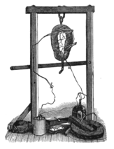
Ane of Henry's electromagnets that could elevator hundreds of pounds, 1830s
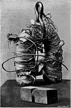
Closeup of a large Henry electromagnet
Danish scientist Hans Christian Ørsted discovered in 1820 that electric currents create magnetic fields. British scientist William Sturgeon invented the electromagnet in 1824.[3] [4] His first electromagnet was a horseshoe-shaped piece of iron that was wrapped with about 18 turns of blank copper wire (insulated wire didn't exist yet). The iron was varnished to insulate it from the windings. When a electric current was passed through the coil, the fe became magnetized and attracted other pieces of atomic number 26; when the current was stopped, it lost magnetization. Sturgeon displayed its power by showing that although it simply weighed vii ounces (roughly 200 grams), it could elevator nine pounds (roughly four kilos) when the electric current of a single-cell power supply was practical. However, Sturgeon'south magnets were weak because the uninsulated wire he used could only be wrapped in a unmarried spaced out layer around the core, limiting the number of turns.
Beginning in 1830, The states scientist Joseph Henry systematically improved and popularised the electromagnet.[5] [6] By using wire insulated by silk thread, and inspired by Schweigger's utilise of multiple turns of wire to make a galvanometer,[7] he was able to wind multiple layers of wire on cores, creating powerful magnets with thousands of turns of wire, including one that could support 2,063 lb (936 kg). The outset major employ for electromagnets was in telegraph sounders.
The magnetic domain theory of how ferromagnetic cores work was showtime proposed in 1906 by French physicist Pierre-Ernest Weiss, and the detailed modern breakthrough mechanical theory of ferromagnetism was worked out in the 1920s by Werner Heisenberg, Lev Landau, Felix Bloch and others.
Applications of electromagnets [edit]
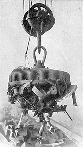
Industrial electromagnet lifting fleck iron, 1914
A portative electromagnet is i designed to simply hold material in place; an example is a lifting magnet. A tractive electromagnet applies a force and moves something.[eight]
Electromagnets are very widely used in electric and electromechanical devices, including:
- Motors and generators
- Transformers
- Relays
- Electrical bells and buzzers
- Loudspeakers and headphones
- Actuators such every bit valves
- Magnetic recording and data storage equipment: record recorders, VCRs, hard disks
- MRI machines
- Scientific equipment such as mass spectrometers
- Particle accelerators
- Magnetic locks
- Musical instrument pickups
- Magnetic separation equipment, used for separating magnetic from nonmagnetic material, for instance separating ferrous metal from other material in chip.
- Industrial lifting magnets
- magnetic levitation, used in a maglev railroad train or trains
- Induction heating for cooking, manufacturing, and hyperthermia therapy
Laboratory electromagnet. Produces 2 T field with twenty A current.


Sextupole focusing magnet in a synchrotron
Unproblematic solenoid [edit]
A common tractive electromagnet is a uniformly-wound solenoid and plunger. The solenoid is a roll of wire, and the plunger is made of a material such as soft iron. Applying a current to the solenoid applies a force to the plunger and may make information technology motility. The plunger stops moving when the forces upon it are balanced. For instance, the forces are balanced when the plunger is centered in the solenoid.
The maximum uniform pull happens when one end of the plunger is at the middle of the solenoid. An approximation for the strength F is[8]

where C is a proportionality constant, A is the cross-exclusive area of the plunger, n is the number of turns in the solenoid, I is the current through the solenoid wire, and l is the length of the solenoid. For units using inches, pounds forcefulness, and amperes with long, slender, solenoids, the value of C is around 0.009 to 0.010 psi (maximum pull pounds per square inch of plunger cross-sectional area).[9] For example, a 12-inch long coil ( l=12 in) with a long plunger of one-square inch cross section ( A=1 inii ) and 11,200 ampere-turns ( n I=11,200 Aturn) had a maximum pull of 8.75 pounds (corresponding to C=0.0094 psi).[10]
The maximum pull is increased when a magnetic cease is inserted into the solenoid. The terminate becomes a magnet that will concenter the plunger; it adds little to the solenoid pull when the plunger is far away but dramatically increases the pull when they are close. An approximation for the pull P is[xi]
![{\displaystyle P=AnI[(nI/l_{\mathrm {a} }^{2}C_{1}^{2})+(C/l)]=(An^{2}I^{2}/l_{\mathrm {a} }^{2}C_{1}^{2})+(CAnI/l)}](https://wikimedia.org/api/rest_v1/media/math/render/svg/d4cfa407a148ad4241d69715e1d834566481aec3)
Here l a is the distance between the end of the stop and the end of the plunger. The additional abiding C ane for units of inches, pounds, and amperes with slender solenoids is about 2660. The 2d term within the bracket represents the same force equally the stop-less solenoid above; the offset term represents the attraction between the stop and the plunger.
Some improvements tin can be fabricated on the basic design. The ends of the finish and plunger are often conical. For instance, the plunger may accept a pointed end that fits into a matching recess in the stop. The shape makes the solenoid'southward pull more uniform as a function of separation. Some other improvement is to add a magnetic render path around the outside of the solenoid (an "iron-clad solenoid").[12] [13] The magnetic return path, just as the finish, has picayune bear on until the air gap is small-scale.
Physics [edit]
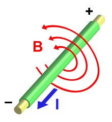
Current (I) through a wire produces a magnetic field (B). The field is oriented according to the right-hand rule.

The magnetic field lines of a current-carrying loop of wire pass through the heart of the loop, concentrating the field there

The magnetic field generated by passing a current through a ringlet
An electric current flowing in a wire creates a magnetic field around the wire, due to Ampere's law (see cartoon below). To concentrate the magnetic field, in an electromagnet the wire is wound into a coil with many turns of wire lying next.[two] The magnetic field of all the turns of wire passes through the center of the coil, creating a strong magnetic field there.[2] A gyre forming the shape of a directly tube (a helix) is chosen a solenoid.[1] [ii]
The direction of the magnetic field through a ringlet of wire can be institute from a grade of the correct-mitt rule.[xiv] [15] If the fingers of the right mitt are curled around the coil in the direction of current period (conventional current, period of positive charge) through the windings, the thumb points in the direction of the field inside the ringlet. The side of the magnet that the field lines sally from is divers to be the north pole.
Much stronger magnetic fields can be produced if a "magnetic core" of a soft ferromagnetic (or ferrimagnetic) material, such every bit iron, is placed inside the roll.[1] [2] [xvi] [17] A core can increase the magnetic field to thousands of times the forcefulness of the field of the coil alone, due to the high magnetic permeability μ of the material.[one] [two] This is chosen a ferromagnetic-core or iron-core electromagnet. All the same, not all electromagnets use cores, and the very strongest electromagnets, such as superconducting and the very loftier current electromagnets, cannot use them due to saturation.
Ampere'southward police force [edit]
For definitions of the variables below, see box at end of article.
The magnetic field of electromagnets in the general instance is given by Ampere's Law:

which says that the integral of the magnetizing field around any closed loop is equal to the sum of the current flowing through the loop. Another equation used, that gives the magnetic field due to each modest segment of current, is the Biot–Savart law. Computing the magnetic field and force exerted by ferromagnetic materials is hard for two reasons. First, because the strength of the field varies from bespeak to point in a complicated style, especially outside the core and in air gaps, where fringing fields and leakage flux must be considered. Second, because the magnetic field B and force are nonlinear functions of the electric current, depending on the nonlinear relation betwixt B and H for the particular core textile used. For precise calculations, calculator programs that can produce a model of the magnetic field using the finite chemical element method are employed.

Magnetic core [edit]
The material of a magnetic cadre (often fabricated of fe or steel) is composed of small regions called magnetic domains that act similar tiny magnets (run into ferromagnetism). Before the electric current in the electromagnet is turned on, the domains in the iron core signal in random directions, so their tiny magnetic fields cancel each other out, and the iron has no big-scale magnetic field. When a current is passed through the wire wrapped around the iron, its magnetic field penetrates the fe, and causes the domains to turn, aligning parallel to the magnetic field, so their tiny magnetic fields add to the wire's field, creating a big magnetic field that extends into the space around the magnet. The effect of the core is to concentrate the field, and the magnetic field passes through the core more easily than it would laissez passer through air.
The larger the current passed through the wire coil, the more the domains marshal, and the stronger the magnetic field is. Finally, all the domains are lined upwards, and further increases in current only cause slight increases in the magnetic field: this phenomenon is chosen saturation.
When the current in the coil is turned off, in the magnetically soft materials that are nearly always used as cores, most of the domains lose alignment and return to a random land and the field disappears. All the same, some of the alignment persists, because the domains have difficulty turning their direction of magnetization, leaving the core a weak permanent magnet. This phenomenon is called hysteresis and the remaining magnetic field is chosen remanent magnetism. The balance magnetization of the cadre tin exist removed by degaussing. In alternating electric current electromagnets, such as are used in motors, the core'southward magnetization is constantly reversed, and the remanence contributes to the motor'southward losses.
Magnetic circuit – the abiding B field approximation [edit]

Magnetic field (green) of a typical electromagnet, with the atomic number 26 cadre C forming a closed loop with 2 air gaps G in information technology.
B – magnetic field in the core
BF – "fringing fields". In the gaps G the magnetic field lines "bulge" out, so the field strength is less than in the core: BF <B
BL – leakage flux; magnetic field lines which don't follow consummate magnetic circuit
Fifty – average length of the magnetic circuit used in eq. one below. It is the sum of the length Lcore in the iron core pieces and the length Lgap in the air gaps G.
Both the leakage flux and the fringing fields get larger equally the gaps are increased, reducing the strength exerted by the magnet.
In many practical applications of electromagnets, such as motors, generators, transformers, lifting magnets, and loudspeakers, the iron core is in the course of a loop or magnetic excursion, maybe broken by a few narrow air gaps.[ii] This is considering the magnetic field lines are in the form of closed loops. Atomic number 26 presents much less "resistance" (reluctance) to the magnetic field than air, so a stronger field tin be obtained if most of the magnetic field's path is within the core.[2]
Since most of the magnetic field is bars within the outlines of the cadre loop, this allows a simplification of the mathematical analysis.[2] See the cartoon at right. A common simplifying assumption satisfied by many electromagnets, which will exist used in this section, is that the magnetic field strength B is constant around the magnetic excursion (within the cadre and air gaps) and nix outside it. Most of the magnetic field will be concentrated in the core fabric (C). Within the core the magnetic field (B) will be approximately compatible across any cantankerous section, so if in add-on the cadre has roughly abiding expanse throughout its length, the field in the core will be constant.[2] This but leaves the air gaps (G), if whatever, between core sections. In the gaps the magnetic field lines are no longer confined by the cadre, so they 'bulge' out beyond the outlines of the cadre before curving dorsum to enter the adjacent piece of core material, reducing the field strength in the gap.[2] The bulges (BF) are called fringing fields.[two] However, equally long as the length of the gap is smaller than the cantankerous section dimensions of the cadre, the field in the gap will be approximately the same every bit in the core. In improver, some of the magnetic field lines (BL) will have 'short cuts' and non pass through the entire core excursion, and thus volition not contribute to the force exerted by the magnet. This also includes field lines that encircle the wire windings just do not enter the core. This is called leakage flux. Therefore, the equations in this department are valid for electromagnets for which:
- the magnetic excursion is a single loop of core material, possibly broken by a few air gaps
- the core has roughly the same cantankerous sectional surface area throughout its length.
- any air gaps between sections of core fabric are not large compared with the cross sectional dimensions of the core.
- in that location is negligible leakage flux
The chief nonlinear feature of ferromagnetic materials is that the B field saturates at a certain value,[2] which is around one.6 to ii teslas (T) for near loftier permeability core steels.[xviii] [xix] [xx] The B field increases quickly with increasing current up to that value, merely above that value the field levels off and becomes almost constant, regardless of how much current is sent through the windings.[2] And so the maximum strength of the magnetic field possible from an iron core electromagnet is express to around 1.6 to 2 T.[18] [20]
Magnetic field created by a current [edit]
The magnetic field created past an electromagnet is proportional to both the number of turns in the winding, N, and the electric current in the wire, I, hence this product, NI, in ampere-turns, is given the name magnetomotive force. For an electromagnet with a unmarried magnetic excursion, of which length L core of the magnetic field path is in the core material and length Fifty gap is in air gaps, Ampere's Law reduces to:[2] [21] [22]

-
- where
- is the magnetic permeability of the core material at the particular B field used.
- is the permeability of free space (or air); notation that in this definition is amperes.


This is a nonlinear equation, considering the permeability of the core, μ, varies with the magnetic field B. For an exact solution, the value of μ at the B value used must be obtained from the core fabric hysteresis curve.[2] If B is unknown, the equation must exist solved past numerical methods. Still, if the magnetomotive force is well above saturation, so the core material is in saturation, the magnetic field will be approximately the saturation value Bsabbatum for the cloth, and won't vary much with changes in NI. For a airtight magnetic circuit (no air gap) most core materials saturate at a magnetomotive force of roughly 800 ampere-turns per meter of flux path.
For most core materials, .[22] So in equation (1) in a higher place, the second term dominates. Therefore, in magnetic circuits with an air gap, the strength of the magnetic field B depends strongly on the length of the air gap, and the length of the flux path in the cadre doesn't matter much. Given an air gap of 1mm, a magnetomotive force of about 796 Ampere-turns is required to produce a magnetic field of 1T.

Strength exerted by magnetic field [edit]
The force exerted by an electromagnet on a section of core textile is:

where is the cross-sectional area of the core. The force equation can exist derived from the energy stored in a magnetic field. Free energy is force times altitude. Rearranging terms yields the equation above.

The 1.6 T limit on the field[eighteen] [20] mentioned above sets a limit on the maximum force per unit core surface area, or magnetic pressure level, an iron-core electromagnet can exert; roughly:

In more intuitive units it'south useful to remember that at ane T the magnetic force per unit area is approximately iv atmospheres, or kg/cm2.
Given a core geometry, the B field needed for a given force tin can be calculated from (2); if it comes out to much more than than 1.6 T, a larger core must exist used.
Closed magnetic circuit [edit]

Cross section of lifting electromagnet like that in to a higher place photo, showing cylindrical construction. The windings (C) are flat copper strips to withstand the Lorentz force of the magnetic field. The core is formed by the thick iron housing (D) that wraps around the windings.
For a airtight magnetic circuit (no air gap), such as would be found in an electromagnet lifting a piece of iron bridged across its poles, equation (1) becomes:

Substituting into (ii), the forcefulness is:

Information technology can be seen that to maximize the forcefulness, a core with a short flux path L and a wide cross-sectional surface area A is preferred (this likewise applies to magnets with an air gap). To achieve this, in applications like lifting magnets (see photo in a higher place) and loudspeakers a flat cylindrical pattern is often used. The winding is wrapped effectually a brusk wide cylindrical core that forms one pole, and a thick metal housing that wraps around the exterior of the windings forms the other part of the magnetic circuit, bringing the magnetic field to the front end to grade the other pole.
Force between electromagnets [edit]
The in a higher place methods are applicable to electromagnets with a magnetic excursion and do not apply when a big part of the magnetic field path is exterior the core. An example would be a magnet with a straight cylindrical core similar the ane shown at the top of this article. For electromagnets (or permanent magnets) with well defined 'poles' where the field lines sally from the core, the strength between two electromagnets can be found using the a magnetic-charge model which assumes the magnetic field is produced past fictitious 'magnetic charges' on the surface of the poles, with pole strength m and units of Ampere-plow meter. Magnetic pole forcefulness of electromagnets can be found from:

The strength betwixt two poles is:

Each electromagnet has two poles, so the total force on a given magnet due to another magnet is equal to the vector sum of the forces of the other magnet'southward poles acting on each pole of the given magnet. This model assumes point-like poles instead of the finite surfaces, and thus information technology merely yields a good approximation when the distance between the magnets is much larger than their diameter.
Side effects [edit]
There are several side furnishings which occur in electromagnets which must be provided for in their blueprint. These generally become more meaning in larger electromagnets.
Ohmic heating [edit]
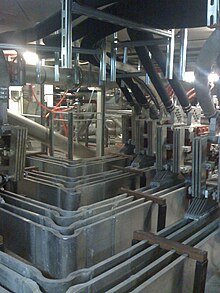
Large aluminum busbars carrying current into the electromagnets at the LNCMI (Laboratoire National des Champs Magnétiques Intenses) loftier field laboratory.
The only power consumed in a DC electromagnet nether steady state conditions is due to the resistance of the windings, and is dissipated as heat. Some large electromagnets require h2o cooling systems in the windings to carry off the waste heat.
Since the magnetic field is proportional to the product NI, the number of turns in the windings Northward and the current I can be called to minimize estrus losses, equally long as their product is constant. Since the power dissipation, P = IiiR, increases with the square of the current just only increases approximately linearly with the number of windings, the power lost in the windings tin can exist minimized by reducing I and increasing the number of turns N proportionally, or using thicker wire to reduce the resistance. For instance, halving I and doubling Northward halves the power loss, as does doubling the area of the wire. In either case, increasing the amount of wire reduces the ohmic losses. For this reason, electromagnets often accept a significant thickness of windings.
However, the limit to increasing Northward or lowering the resistance is that the windings take upward more room between the magnet's core pieces. If the area available for the windings is filled up, more turns require going to a smaller bore of wire, which has college resistance, which cancels the reward of using more turns. Then in large magnets in that location is a minimum corporeality of heat loss that can't be reduced. This increases with the square of the magnetic flux Bii .
Inductive voltage spikes [edit]
An electromagnet has significant inductance, and resists changes in the electric current through its windings. Whatsoever sudden changes in the winding current crusade big voltage spikes across the windings. This is because when the current through the magnet is increased, such as when it is turned on, energy from the circuit must be stored in the magnetic field. When it is turned off the energy in the field is returned to the circuit.
If an ordinary switch is used to control the winding current, this tin cause sparks at the terminals of the switch. This does non occur when the magnet is switched on, because the limited supply voltage causes the electric current through the magnet and the field energy to increase slowly, merely when information technology is switched off, the energy in the magnetic field is suddenly returned to the excursion, causing a big voltage fasten and an arc across the switch contacts, which can damage them. With pocket-sized electromagnets a capacitor is sometimes used across the contacts, which reduces arcing by temporarily storing the current. More oftentimes a diode is used to forestall voltage spikes by providing a path for the electric current to recirculate through the winding until the energy is dissipated as rut. The diode is connected across the winding, oriented and then it is reverse-biased during steady state functioning and does not conduct. When the supply voltage is removed, the voltage spike forward-biases the diode and the reactive current continues to menses through the winding, through the diode and back into the winding. A diode used in this style is called a freewheeling diode or flyback diode.
Large electromagnets are usually powered by variable current electronic power supplies, controlled by a microprocessor, which prevent voltage spikes past accomplishing current changes slowly, in gentle ramps. It may take several minutes to energize or deenergize a big magnet.
Lorentz forces [edit]
In powerful electromagnets, the magnetic field exerts a forcefulness on each turn of the windings, due to the Lorentz forcefulness acting on the moving charges within the wire. The Lorentz force is perpendicular to both the axis of the wire and the magnetic field. It can be visualized as a pressure betwixt the magnetic field lines, pushing them apart. It has two effects on an electromagnet'south windings:

- The field lines within the axis of the coil exert a radial force on each turn of the windings, tending to button them outward in all directions. This causes a tensile stress in the wire.
- The leakage field lines betwixt each turn of the curlicue exert an bonny forcefulness between adjacent turns, tending to pull them together.[ citation needed ]
The Lorentz forces increment with B2 . In large electromagnets the windings must exist firmly clamped in place, to prevent motion on power-up and power-down from causing metallic fatigue in the windings. In the Bitter design, beneath, used in very loftier-field enquiry magnets, the windings are constructed every bit flat disks to resist the radial forces, and clamped in an centric direction to resist the centric ones.
Core losses [edit]
In alternating current (Air conditioning) electromagnets, used in transformers, inductors, and AC motors and generators, the magnetic field is constantly changing. This causes energy losses in their magnetic cores that is dissipated every bit heat in the core. The losses stem from two processes:
- Boil currents: From Faraday's law of induction, the changing magnetic field induces circulating electric currents within nearby conductors, called boil currents. The free energy in these currents is dissipated as estrus in the electrical resistance of the conductor, then they are a cause of energy loss. Since the magnet'due south fe core is conductive, and virtually of the magnetic field is concentrated there, eddy currents in the cadre are the major problem. Boil currents are airtight loops of current that catamenia in planes perpendicular to the magnetic field. The energy dissipated is proportional to the area enclosed by the loop. To forbid them, the cores of Air conditioning electromagnets are made of stacks of thin steel sheets, or laminations, oriented parallel to the magnetic field, with an insulating blanket on the surface. The insulation layers prevent eddy current from flowing between the sheets. Whatever remaining eddy currents must flow within the cross-department of each individual lamination, which reduces losses greatly. Some other culling is to utilize a ferrite core, which is a nonconductor.
- Hysteresis losses: Reversing the direction of magnetization of the magnetic domains in the core material each cycle causes energy loss, considering of the coercivity of the material. These losses are chosen hysteresis. The energy lost per wheel is proportional to the area of the hysteresis loop in the BH graph. To minimize this loss, magnetic cores used in transformers and other Air conditioning electromagnets are fabricated of "soft" low coercivity materials, such as silicon steel or soft ferrite. The energy loss per bicycle of the AC current is constant for each of these processes, so the power loss increases linearly with frequency.
High-field electromagnets [edit]
Superconducting electromagnets [edit]
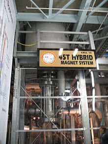
The most powerful electromagnet in the globe, the 45 T hybrid Bitter-superconducting magnet at the US National Loftier Magnetic Field Laboratory, Tallahassee, Florida, USA
When a magnetic field higher than the ferromagnetic limit of 1.vi T is needed, superconducting electromagnets can exist used. Instead of using ferromagnetic materials, these apply superconducting windings cooled with liquid helium, which bear electric current without electrical resistance. These permit enormous currents to menstruation, which generate intense magnetic fields. Superconducting magnets are limited by the field forcefulness at which the winding material ceases to be superconducting. Electric current designs are limited to 10–20 T, with the current (2017) record of 32 T.[23] [24] The necessary refrigeration equipment and cryostat make them much more expensive than ordinary electromagnets. Even so, in high power applications this can be showtime past lower operating costs, since afterwards startup no power is required for the windings, since no energy is lost to ohmic heating. They are used in particle accelerators and MRI machines.
Biting electromagnets [edit]
Both iron-core and superconducting electromagnets accept limits to the field they can produce. Therefore, the most powerful homo-made magnetic fields take been generated by air-core nonsuperconducting electromagnets of a design invented by Francis Biting in 1933, called Bitter electromagnets.[25] Instead of wire windings, a Bitter magnet consists of a solenoid fabricated of a stack of conducting disks, arranged so that the electric current moves in a helical path through them, with a pigsty through the center where the maximum field is created. This design has the mechanical force to withstand the farthermost Lorentz forces of the field, which increase with B 2. The disks are pierced with holes through which cooling water passes to carry away the rut caused by the loftier current. The strongest continuous field achieved solely with a resistive magnet is 37.five T as of 31 March 2014[update], produced past a Bitter electromagnet at the Radboud Academy High Field Magnet Laboratory in Nijmegen, the Netherlands.[26] The previous record was 35 T.[24] The strongest continuous magnetic field overall, 45 T,[25] was accomplished in June 2000 with a hybrid device consisting of a Biting magnet inside a superconducting magnet.
The factor limiting the strength of electromagnets is the disability to misemploy the enormous waste heat, so more powerful fields, up to 100 T,[24] take been obtained from resistive magnets by sending cursory pulses of loftier current through them; the inactive menstruum after each pulse allows the heat produced during the pulse to be removed, before the next pulse.
Explosively pumped flux compression [edit]

A hollow tube type of explosively pumped flux compression generator. The hollow copper tube acts like a single turn secondary winding of a transformer; when the pulse of electric current from the capacitor in the windings creates a pulse of magnetic field, this creates a potent circumferential electric current in the tube, trapping the magnetic field lines within. The explosives then collapse the tube, reducing its diameter, and the field lines are forced closer together increasing the field.
The most powerful manmade magnetic fields[27] have been created by using explosives to compress the magnetic field inside an electromagnet as it is pulsed; these are called explosively pumped flux compression generators. The implosion compresses the magnetic field to values of around 1000 T[25] for a few microseconds. While this method may seem very destructive, it is possible to redirect the brunt of the smash radially outwards so that neither the experiment nor the magnetic structure are harmed. These devices are known equally destructive pulsed electromagnets.[28] They are used in physics and materials scientific discipline enquiry to written report the backdrop of materials at high magnetic fields.
Definition of terms [edit]
| Term | Significance | Unit |
| cross sectional area of core | square meter | |
| Magnetic field (Magnetic flux density) | tesla | |
| Force exerted past magnetic field | newton | |
| Magnetizing field | ampere per meter | |
| Current in the winding wire | ampere | |
| Full length of the magnetic field path | meter | |
| Length of the magnetic field path in the cadre material | meter | |
| Length of the magnetic field path in air gaps | meter | |
| Pole strength of the electromagnet | ampere meter | |
| Permeability of the electromagnet core textile | newton per square ampere | |
| Permeability of free space (or air) = 4π(10−7) | newton per foursquare ampere | |
| Relative permeability of the electromagnet core material | - | |
| Number of turns of wire on the electromagnet | - | |
| Distance between the poles of 2 electromagnets | meter |


Encounter likewise [edit]
- Dipole magnet – the about basic form of magnet
- Electromagnetism
- Electropermanent magnet - a magnetically difficult electromagnet arrangement
- Explosively pumped flux compression generator
- Field coil
- Magnetic bearing
- Pulsed field magnet
- Quadrupole magnet – a combination of magnets and electromagnets used mainly to affect the motion of charged particles
References [edit]
- ^ a b c d e Nave, Carl R. (2012). "Electromagnet". Hyperphysics. Dept. of Physics and Astronomy, Georgia Country Univ. Archived from the original on September 22, 2014. Retrieved September 17, 2014.
- ^ a b c d eastward f grand h i j yard l grand n o p Merzouki, Rochdi; Samantaray, Arun Kumar; Pathak, Pushparaj Mani (2012). Intelligent Mechatronic Systems: Modeling, Command and Diagnosis. Springer Science & Business concern Media. pp. 403–405. ISBN978-1447146285. Archived from the original on 2016-12-03.
- ^ Sturgeon, W. (1825). "Improved Electro Magnetic Appliance". Trans. Royal Society of Arts, Articles, & Commerce. 43: 37–52. cited in Miller, T.J.Eastward (2001). Electronic Control of Switched Reluctance Machines. Newnes. p. seven. ISBN978-0-7506-5073-1. Archived from the original on 2016-12-03.
- ^ Windelspecht, Michael. Groundbreaking Scientific Experiments, Inventions, and Discoveries of the 19th Century Archived 2017-01-11 at the Wayback Machine, xxii, Greenwood Publishing Grouping, 2003, ISBN 0-313-31969-3.
- ^ Cavicchi, Elizabeth. "Series and Parallel Experimenting with Electromagnets" (PDF). Pavia Projection Physics, Univ. of Pavia, Italian republic. Archived (PDF) from the original on March 15, 2016. Retrieved August 22, 2015.
- ^ Sherman, Roger (2007). "Joseph Henry's contributions to the electromagnet and the electric motor". The Joseph Henry Papers. The Smithsonian Establishment. Archived from the original on 2012-06-08. Retrieved 2008-08-27 .
- ^ "Schweigger Multiplier – 1820". Maglab. National High Magnetic Field Laboratory. Archived from the original on 17 October 2017. Retrieved 17 October 2017.
- ^ a b Dawes, Chester L. (1967). "Electric Engineering science". In Baumeister, Theodore (ed.). Standard Handbook for Mechanical Engineers (7th ed.). McGraw-Hill. p. 15-105.
- ^ Dawes 1967, p. fifteen-105–15-106
- ^ Dawes 1967, p. 15-106, Table 25
- ^ Dawes 1967, p. 15-106
- ^ Dawes 1967, p. xv-106
- ^ Underhill, Charles R. (1906). The Electromagnet. D. Van Nostrand. p. 113. Archived from the original on 2016-05-01.
- ^ Millikin, Robert; Bishop, Edwin (1917). Elements of Electricity. Chicago: American Technical Gild. pp. 125.
- ^ Fleming, John Ambrose (1892). Brusque Lectures to Electrical Artisans, 4th Ed. London: Eastward.& F. N. Spon. pp. 38–40. Archived from the original on 2017-01-11.
- ^ Gates, Earl (2013). Introduction to Bones Electricity and Electronics Technology. Cengage Learning. p. 184. ISBN978-1133948513. Archived from the original on 2017-01-10.
- ^ Shipman, James; Jerry, Wilson; Todd, Aaron (2009). Introduction to Physical Science (12 ed.). Cengage Learning. pp. 205–206. ISBN978-1111810283. Archived from the original on 2017-01-11.
- ^ a b c "Saturation flux levels of various magnetic materials range up to 24.five kilogauss" (2.5 T) p.ane "Silicon steel saturates at nearly 17 kilogauss" (one.seven T) p.iii Pauley, Donald E. (March 1996). "Power Supply Magnetics Office 1: Selecting transformer/inductor core fabric". Power Conversion and Intelligent Motion. Archived from the original on Dec 24, 2014. Retrieved September 19, 2014.
- ^ The about widely used magnetic core material, three% silicon steel, has saturation induction of 20 kilogauss (ii T). "Material Properties, 3% grain-oriented silicon steel". Catalog. Magnetic Materials Co. 2013. p. 16. Archived from the original on September 20, 2014. Retrieved September 19, 2014.
- ^ a b c "Magnetic steel fully saturates at about 2 T" Curt, Thomas Allen (2003). Electric Power Distribution Handbook. CRC Press. p. 214. ISBN978-0203486504.
- ^ Feynman, Richard P. (1963). Lectures on Physics, Vol. 2. New York: Addison-Wesley. pp. 36–9 to 36–11, eq. 36–26. ISBN978-8185015842.
- ^ a b Fitzgerald, A.; Kingsley, Charles; Kusko, Alexander (1971). Electric Machinery, third Ed. Usa: McGraw-Colina. pp. 3–v.
- ^ "32 Tesla All-Superconducting Magnet". National High Magnetic Field Laboratory, United states. 2018.
- ^ a b c "Magazine Lab World Records". Media Center. National Loftier Magnetic Field Laboratory, USA. 2008. Archived from the original on 2008-10-07. Retrieved 2008-08-31 .
- ^ a b c Coyne, Kristin (2008). "Magnets: from Mini to Mighty". Magnet Lab U. National High Magnetic Field Laboratory. Archived from the original on 2008-09-17. Retrieved 2008-08-31 .
- ^ "HFML sets world record with a new 37.five tesla magnet". High Field Magnet Laboratory. 31 March 2014. Archived from the original on four September 2015. Retrieved 21 May 2014.
- ^ "What is the strongest magnet in the earth?". Noon magnets. November 2014. Archived from the original on February v, 2017. Retrieved February 5, 2017.
- ^ Coyne, Kristin (2008). "7. Pulsed Magnets: Cursory Shining Moments". Magnets from Mini to Mighty. National High Magnetic Field Laboratory. Archived from the original on 2014-12-xx. Retrieved 2014-05-21 .
External links [edit]
- Magnets from Mini to Mighty: Primer on electromagnets and other magnets National High Magnetic Field Laboratory
- Magnetic Fields and Forces Cuyahoga Customs College
- Key Relationships Schoolhouse of Geology and Geophysics, University of Oklahoma

Source: https://en.wikipedia.org/wiki/Electromagnet
Posted by: dupreexer1976.blogspot.com
0 Response to "What Is The Effect Of Putting A Ferromagnetic Material Inside The Coil Of A Solenoid?"
Post a Comment